

crazypoet
-
Posts
826 -
Joined
-
Last visited
Content Type
Profiles
Forums
Events
Gallery
Everything posted by crazypoet
-
Looking at this, the 308bit console seems a bit "soft" - does it look like that to you? I like the idea of raised buttons and switches, but not if they look like melting butter... or is it just the lighting?
-
The Non-LSM section is open to topics that fall otherwise out of scape. post away!
-
Welcome to the asylum!
-
I look forward to each update as you go - this is great work. I second the beer-can request, if only to show that you have the occasional bit of "refreshment" while working this beast!
-
Reached a milestone today - all the plumbing is done, with engine and boiler finished and installed. I need to do a bit of detail work on the pipes to bring everything together - these parts were done months apart with some different techniques and I need to blend in the differences. i still need to finish making the various tools, rig the gun, mast, flag and stack. I finally received the flag I ordered...only to find I'd specified the wrong [expletive deleted] size... AAAARRRRGHHHH!!!! So... I now have the *proper* size on the way, along with some lovely brass turnbuckles for the stack tie-downs. This adventure in online shopping *did* give me a chance to realize that the toggle-and-loop rigging I had for the flag was a bit out of scale. I'm redoing that - using brass pins rather than 1/32" brass rod for the toggles. Nobody uses 3/4" diameter toggles to hang a flag... don't know what I was thinking!
-
Are you going to have the suspension fixed, or build it to articulate? watching this build "over your shoulder" is a joy - thank you for sharing all the little steps
-
Thanks for the info and the comparisons - I should have caught on sooner about the similarities to heavy card and paper. [smacks forehead] That said, the paper kits that I've seen were aimed at kids - until I saw that Model-Kom kit you referenced above! I'm impressed with what can be done with good patterns
-
Just thought of a question - something that you've obviously mastered, but that I have yet to deal with... That is forming and gluing compound curves from flat/straight plastic strip. I've been utterly spoiled in that department as most of my scratch-building has been in either metal or wood, both of which are simple to bend and hold their shape after the fact. When I've done scratch-building with plastic it's been either straight bits or pieces thin and small enough that I could use CA to hold them. So what is your approach to clamping/fixing fairly thick plastic curves/twists/bends while plastic cement dries?
-
Love the work! I've also struggled with large-scale rivets. Pinheads, resin decals... I feel your pain! i'm going to look up your source at MasterClub - thank you for the reference!
-
STAR WARS "Millennium Falcon" - 1/72 by Revell Master Series
crazypoet replied to elmarriachi's topic in Non LSM 'WIP
Sweeeeet! -
This is great work, and an interesting approach - watching with interest!
-
Starting to come together... a bit bit of rust for the condenser... installation - engine, condenser and prop the hot box and engine plumbing are next. There are three pipes that run from the engine down into the deck, plus one that will run between the engine and the boiler. i'm using brass tubing and white metal elbows, painted with Alclad exhaust manifold and Vallejo light rust - it's giving me what I *hope* is a good approximation of iron pipes and bronze fittings. The prop shaft got dressed up with copper electroplate and fittings made from both larger-diameter brass tube and some heat-shrink tube, both covered in graphite.
-
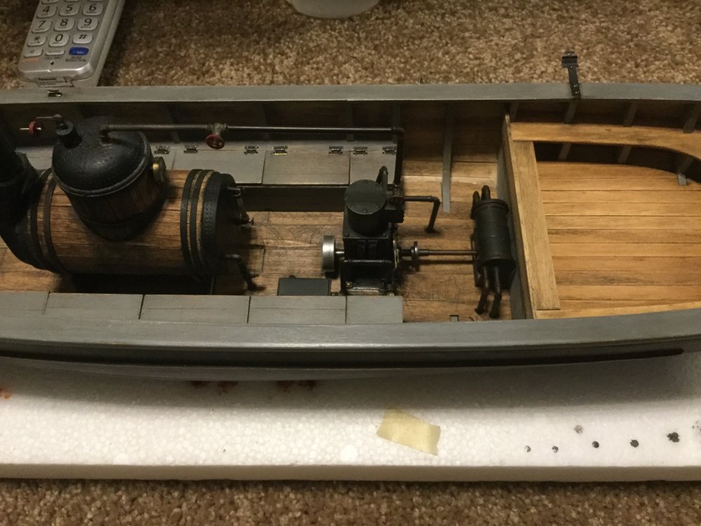
So, yeah, I moved the mast fitting... I just couldn't wrap my brain around the offset - it never did look right. so... patch, paint, drill... I had to re-create the original wood grain in the boards where I patched the hole. I found that the back edge of an x-acto blade did the trick nicely. I've not yet applied the last stain wash over the patch, but it's starting to blend in. I'm still waiting on the flags (I understand that they cleared Customs today, so should arrive Monday or Tuesday) so the mast isn't ready for installation. I'll do pics when it's ready - I'm pleased with the way it looks so far, but I need the flags and rigging done before it will be ready for a close-up. I found that a conveniently-sized washer, a bit of brass tube, raised-resin rivet decals and some heat-shrink tubing made for a quite nice mount for the thing - watch this space for further details... while I'm waiting for the flags... here's the first test fitting of the internal components, checking spacing and alignment of the plumbing: there is a bit of trimming necessary in the decking - the deck planks I used are a bit thicker than the original kit specs so I'll have to cut the planks and inset the engine baseplate to make everything level. i also will have to drill through the deck planks for each steam and water pipe. the pipes will pass through the decking and disappear into the depths; fortunately I don't have to do all the sub-deck plumbing. While working these odds and ends, I found good photos online of the different types of tools that would have been carried onboard. Spanners, coal shovel and valve keys for the engine/boiler, caulking hammers and carpenter tools for the hull and suchlike. I'll need to scratchbuild all of those, since such scale tools as I've been able to find to-date are just not right - they seem all to be dollhouse accessories made to look decent from a distance, but which fail miserably under close inspection. I found a perfect anchor, though, which makes me very happy
-
STAR WARS "Millennium Falcon" - 1/72 by Revell Master Series
crazypoet replied to elmarriachi's topic in Non LSM 'WIP
I love this work, and look forward to watching as always an inspiration -
I finished weathering the hull and gave it a light dull coat to seal things in. Today I stain-washed the deck; when the stain cures it will get a bit of weathering touch-up and a dull coat as well. I'm getting close to happy with the mast. It's not *completely* finished and the cotton flags I ordered have not yet arrived, so please forgive the state of the rigging - a bit of a tangeled mess at the moment! When the flags arrive, I'll finish the loop-and-toggle rigging and set the mast. I may yet move it behind the tiller - I'm completely undecided as of yet. It would be "correct" in either location, I just have to see which feels *right* next step... machinery
-
Ok, ok, I did it. I sprung for DeAgostini Millenium Falcon. Plus some extras. I won't even *think* about starting the build until I have at least the first half of the shipments, but the first load arrived today, giving me an idea about what to expect. the Falcon bits: And the Extras: These are PE and decal sets for the cockpit, hold, turret interiors and main engine screen. All by ParaGrafix. I also have some extra cockpit lighting enroute, and I'm looking at some other bits as well. This kit gives me something that's just plain fun to which to look forward.
-
I'm interested in your approach to the cockpit. The kit version, well, stinks. I've already ordered a PE upgrade, but just saw a full 3D printed version that improves on the PE. Which way did you go on yours? i'm not looking for movie-exact, but having lumps and bumps and switches seems sorta basic
-
I have the HK G kit in my stash, which I plan to build as a tribute to a specific craft and crew, lost over Czechoslovakia n March of 1945. The pilot was the grandfather of a close friend, so I want to be sure I get it right
-
RAAF Kingfisher
crazypoet replied to simmo.b's topic in LSM 1/32 and Larger Aircraft Ready for Inspection
Nicely done! -
-
-
-
-
-
