
HubertB
-
Posts
2,988 -
Joined
-
Last visited
Content Type
Profiles
Forums
Events
Gallery
Everything posted by HubertB
-

GWH Curtiss P-40B; The Flying Tigers
HubertB replied to Peterpools's topic in LSM 1/35 and Larger Work In Progress
On the right track, Peter 👍 ! Hubert -
Although I agree the national Post Offices are killing rapidly international parcels with more and more outrageous shipping costs, I’ll stick to giving a kit rather than a purchase voucher, just for the sake of keeping the Christmas spirit of exchanging gifts … Just my of course Hubert
-
Fisher F9F Twogar done
HubertB replied to JohnB's topic in LSM 1/32 and Larger Aircraft Ready for Inspection
VERY nice Twogar, John. the more I see your builds, the more I am getting convinced to let go my procrastinating AMS philosophy… well, almost 😉 Hubert -
HK Models 1:32 A-20G Test Sample - WIP
HubertB replied to Fran's topic in LSM 1/35 and Larger Work In Progress
I don't want to be in the bemoaning camp, as I am sure it is the preferred version of most, but I personally only liked the glass-nosed versions. Looking forward to your build, Fran. Hubert -
I’m in. I had books to give away this year, but I understand they are not the preferred choice this year. Fine by me, but I need more time to find something suitable. Hubert
-
Well, just saw on LSP a new opportunity for the GB: Halberd Models will release in January 23 a 1/32 Curtiss SC-1 Seahawk ! Hubert
-
This is why I hate tiny models. Or how do I do this?
HubertB replied to ScottsGT's topic in Hints & Tips
My tip : make it an inflight display… HTH 😂 Hubert- 12 replies
-
- 10
-

-

-
The important detail on the IP is on the left (the rectangular shaped indicators). They were the warning lights for the overheating of the evaporative cooling system. If red, the message was « Slow down immediately and land asap ». Udet ignored those lights during his successful world speed record run. He told afterwards he had not been briefed about their significance … I had the kit with the idea of converting it to the speed-record V8. Then changed my mind and resold it: too much work creating a new wing and, mostly, the dreaded swastika when finished (what was I thinking when I bought the kit ? Can I pretend, like Udet, I did not know it was adorned with a swastika and I did not know what it meant 😕 ?) To finish on the kit’s cockpit, it’s basic but a good representation of the original, as far as it’s known. Hubert
-
Y’all still good on Dec 1 GB start, or wait till Jan 1?
HubertB replied to Clunkmeister's topic in Modelling Discussion
You could imagine a dio with a ditched Spitfire in the Channel … maybe even with a Walrus coming to the rescue Hubert -
Y’all still good on Dec 1 GB start, or wait till Jan 1?
HubertB replied to Clunkmeister's topic in Modelling Discussion
Objectively, considering what I have planned for December, I won’t do much modeling during this month…not that I am that good in GBs, on top Hubert -
1:32nd scale Nieuport XVII (17) C.1
HubertB replied to sandbagger's topic in LSM 1/35 and Larger Work In Progress
Hubert -
Looks like the Sith version of R2D2 ... Hubert
-
About the same … the casino always wins 😂 Hubert
-
i must be a very rare breed. I spent 4 days in Las Vegas back in 1997, and did not play one cent ... (must have kept it for the stash ) Hubert
-
Well, I'd say you follow a real life logical sequence. Oil streaks can come at any time, whatever the state of the landing field. Plus they are more difficult to clean off than field-induced dirt and grime ... Good job overall, Gary 👍 ! Hubert
-
Micro-Mir have announced an Brantly B2, and furthermore in the « proper » 1/32 scale. Now we need a James Bond (Sean Connery) figure Hubert
-
Cool project Rog. I went through this process during the Covid, in 2020. Then we decided the area was too much exposed to humid and fresh oceanic winds … After one year, we put up the house for sale, sold it in less than 6 months, with a VERY good profit - which explains why I now have a nice car, but not the garage to park it into 😉. The idea was to start a new building project 120 Kim’s South-East of the first house. We bought a nice plot … but then « small details » like a war in the Eastern confines of Europe, an inflation shock, the lack of building materials in Portugal, manpower shortages in the construction sector, and the protracted authorization process in the new area had us change our mind this summer… So now we are buying a ready-built house, albeit with transformation works which will last a few months. 10 kms from where the plot was…The good news is we have resold the plot very well. Wishing you the best on this one Rog. Hubert
-
1) It’s the only He-100 kit in 1/32. This alone makes it worth it, if you want to build a He-100 kit. 2) Given the lack of pics (I know of only one of the IP and port side of the cockpit) as outlined by Gary, you can go to town on detailing the cockpit to your liking … Hubert
-
6 dead overall. Hubert
-
She’s looking good, Gary. I would never have thought I’d say that one day, but maybe you can try reinforcing the details by more wash ? If you can use a washable wash, then maybe you could reverse the effect if you do not like it ? Hubert
-
I have read mixed reports about it. Looks like a one-man operation, with cottage-industry type of decal printing. When I checked their « YIPEE » P-38 decal sheet, it was wrong in many aspects, including wrong typo, wrong representation of the Yipee name, etc. Hubert
-
I see, yes. But the issue is HGW rivets, even if it’s very small are in relief protruding from the kit’s surface, not recessed as IRL. This said, the area around the HGW rivets will appear darker than the silver-colored rivets … we are talking perceptions here, just like in figure painting… Maybe a darker wash along rivets lines would help creat the effect you are after ? Hubert
-
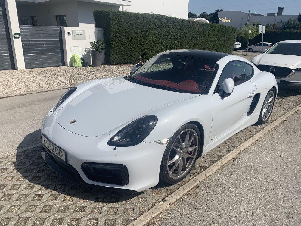
I got it in February. It’s a Porsche 981 Cayman GTS. Carrera Weiss outside with Carrera Rot interior leather trim … Hubert
- 2,035 replies
-
- 9
-
-
- car related stuff
- anything about cars
- (and 6 more)
-
I’ve read the way to make the HGW rivets more visible was to scrub the (thin) coat of paint with a scrubbing sponge (the kitchen type) Hubert
-
"Normal state" ? Hubert