Craigyboy Posted August 31, 2022 Author Share Posted August 31, 2022 2 hours ago, Spitfire said: Amazing attention to detail, looks fabulous. Cheers Dennis Thanks Dennis, testing the eyesight though 1 Link to comment Share on other sites More sharing options...
Kaireckstadt Posted August 31, 2022 Share Posted August 31, 2022 Amazing work Craig ! 2 Link to comment Share on other sites More sharing options...
Craigyboy Posted August 31, 2022 Author Share Posted August 31, 2022 5 minutes ago, Kaireckstadt said: Amazing work Craig ! Thanb you! 1 Link to comment Share on other sites More sharing options...
Craigyboy Posted September 8, 2022 Author Share Posted September 8, 2022 Well, it's been quite a few days! Over last weekend I was almost in despair with this flipping model and its vagaries. I started some work on the flaps and TBH, they are a pile of poo right OOB. As you can see the ejector marks are an absolute nightmare. They're everywhere all over the open surfaces of the flaps and pain to get to. These are the upper surfaces of the flaps but the lower surfaces are just as bad. Also, there are errors on the lower flaps . The holes drilled out to lighten the flap weight on the outboard flap stop short by 6 holes. They should extend right to the end of the flap but they don't. Lord knows why. The whole thing was finished off by the joins of the flap strengthening struts. They should be a nice tight right angle but every one as you can see they're a button shape due to poor moulding. It was so bad that I did a bit of browsing and found an old WWII shutdown procedure which said the flaps should be closed after landing before taxying. "Great!" I thought. I can get away with working flaps up. I don't like it as the flaps are an area you can go to town on but the time needed for these would be horrendous, so, I glued them up retracted. I was also getting ready for closing up the undercarriage so I dirtied up the area that can be seen through the crew door and spiced up the flare chute a little then went ahead and started the closure. Weekend done, job done, ready to move on next week......or so I thought. This Tuesday was a very special day. I was invited down to RAF Coningsby to see the BBmF aircraft by the current Flight Eng of PA474 who's been following my build and giving lots of support and advice. I expected a look round and to take some pictures but my word it was so much more than that! Instead of walking round the perimeter of the hanger as all the other visitors were, being told about the aircraft and having what would have been a great time, I was taken all round the aircraft, up close, touching the damn things for around two hours by the said flight engineer, who I won't name because some people don't like it. All I will say is "Thanks Chap". I can honestly say I could've died happy right there and then. I didn't take many photos as I'm not an avid photo taker. I feel you lose the moment if you're obsessed with taking snaps and, anyway, the knowledge and info that was being chucked at me demanded I listen and learn for every moment I was there. I touched the little plate covering the Battle of Britain bullet hole on P7350 and I had to hold back the tears. Then we finally got to the lady, the beautiful P474 and Eng's pride and joy. We went all the way around, under the bomb bay, inside the wheel wells and studied the flaps......... The flaps, I had to ask didn't I? "When you shutdown the aircraft, is it flaps up or down?" I asked. "Oh, flaps down. It takes the pressure from the hydraulic pumps so nothing can move". was the reply "Bloody hell" I said "you've just made me a shed load of work"......and the subject of a whole post to come I genuinely thought that was it but no. "Are you clear on board?" was the question to the technician. "Yep" was the reply so onboard we went! Well hidden tears were in the eyes again so photos were hard to take but I got a few. He described her as a "reverse TARDIS" and it's true. She's so huge on the outside but climb aboard and she's so small. I'm 5' 8" and I bashed my head four times. There is just no space at all. We went aft then forward, all the way to the cockpit. Information and procedures flowing the whole time. I felt like a crew in 1943 learning the aircraft. It was fantastic and fascinating. I'm from an electro-mechanical maintenance background so I lapped it all up. As I say, we reached the cockpit and he said "take a seat". "Bloody hell!, there's only one" I thought ( we were past the nav's seat and the eng's seat was up) "THAT one?" Tears again though I'm good at hiding it. I just go quiet. It's even tight getting your legs either side of the control column. So tight everywhere. I thought of the guys trying to get out of a plunging aircraft in the pitch dark, possibly on fire, and I realised why not many did. The motto of BBMF is "Lest We Forget" and it was never more at the forefront of my mind than at that moment. We went through startups, fire procedures, shutdowns. The obligatory "Rad Shutters Auto" and the reasons why of course. He signed my Haynes manual and I took the cockpit section of my Dam Buster Lanc for him to have a peek at in the flesh. A memorable day I'll never, ever forget. Thanks again chap and I'm always up for a day doing an oil change if you're ever short So, to finish off this one, a couple of shots I did take. One showing the bloody size of her and a couple from the pilot's seat. Still can't believe I'm saying that.... Flaps next 7 2 Link to comment Share on other sites More sharing options...
Craigyboy Posted September 9, 2022 Author Share Posted September 9, 2022 So what about these 'ere flaps? As you saw earlier, they're a disaster. So first to the removal of the ejector pins. Not easy but the sharpened electrical testing screwdriver I used on the bomb bay came in handy again. Getting in to sand wasn't easy either but the bulk of the flaps interior are going to be black (P474's are so that's good enough for me!) with some subtle wear and scratching, remember these were not very old aircraft. The right angle joins with awful joints were another matter. I came up with a method as follows: First, cut down each side of the "joint" to free that plastic Next cut across the top of the "button" Clean out the corners to give a 90 degree angle ie get rid of the button. file across the top of each front to back strut to regain its shape. Hopefully, after you've done the lot, it'll look acceptable. Top is the adjusted one, bottom as it comes off the sprue. Now we need to address the missing holes we talked about in the last post. There are six missing and they're shallow and flat so simply drilling was out. Since I don't have a spare milling machine lying around, the only thing I could think to do was to create a little fillet in thin plasti card, put the holes in and let it into the flap. Then I could file it down to try and make an acceptable bodge job of it. So first I cut a bit of 0.5mm card 31mm by 6mm. The holes sit VERY close to the lower edge but I set them a little high so there was no chance of the holes splitting and then I could adjust when the fillet was in. Next, mark and gentleman's parts the positions of the holes. Now, we need a hole of 2.4mm in diameter. It won't drill (I tried) the card is too thin so I used a rat tailed file, put a bit of tape around it at 2.4 mm in diameter and eased the holes out from there Then it's a simple matter to glue it into place, file the edges down to blend it in as well as possible then prime, check and spray aluminium to get ready for chipping. It's not perfect but better than having six holes missing Only took 10 hours....... Lastly today I started checking the fit of the wheel bays into the wing. Because I cut out all the plastic between the struts it means you can see the fuel tanks in the wings so I had to fabricate those too. I used a plastic bottle middle which is bendable to match the wing shape. Colour wise, I've seen some done in green and others in a red primer. I've gone for red primer as it seems that early Lancs had red primer and later ones interior green (P474 has green ones). You can see the message "STAND TANK THIS END" on the tank so I put that on as well using individual white letter decals about 1.5mm high. The eyes are NOT being treated kindly at the minute. Thanks for looking as ever. 7 2 Link to comment Share on other sites More sharing options...
HubertB Posted September 10, 2022 Share Posted September 10, 2022 It must have been a tremendous experience 👍 ! Good for you, and I suppose vey motivating for your build. Keep it going Hubert 3 Link to comment Share on other sites More sharing options...
Craigyboy Posted September 10, 2022 Author Share Posted September 10, 2022 7 minutes ago, HubertB said: It must have been a tremendous experience 👍 ! Good for you, and I suppose vey motivating for your build. Keep it going Hubert Thanks Hubert. It really was. And humbling too. 2 Link to comment Share on other sites More sharing options...
BlrwestSiR Posted September 11, 2022 Share Posted September 11, 2022 Nice job fixing the ejector pin marks on the flaps. There are several mechanical pencil style sanders on the market that might be of use in the future. They're available in different widths and grits. I'll try to grab a pic of two of them next time I'm at the bench. Carl 2 Link to comment Share on other sites More sharing options...
Craigyboy Posted September 11, 2022 Author Share Posted September 11, 2022 7 minutes ago, BlrwestSiR said: Nice job fixing the ejector pin marks on the flaps. There are several mechanical pencil style sanders on the market that might be of use in the future. They're available in different widths and grits. I'll try to grab a pic of two of them next time I'm at the bench. Carl Thanks Carl. Would be MOST useful 2 Link to comment Share on other sites More sharing options...
BlrwestSiR Posted September 11, 2022 Share Posted September 11, 2022 Here you go. These ones are made by Galaxy Hobby and are 3mm in width and are 400, 600 and 800 grit. 2 Link to comment Share on other sites More sharing options...
Craigyboy Posted September 11, 2022 Author Share Posted September 11, 2022 Just now, BlrwestSiR said: Here you go. These ones are made by Galaxy Hobby and are 3mm in width and are 400, 600 and 800 grit. Thankyou soo much. They will be perfect for the plague of ejector pins 2 Link to comment Share on other sites More sharing options...
Craigyboy Posted September 29, 2022 Author Share Posted September 29, 2022 Time for an update I think! So, after the flap fiasco it was time to get the cockpit and fuselage together. The instructions say to keep the cockpit halves separate, glue them to the fuselage halves then glue the whole thing together. I felt that was just too much lining up of some very delicate parts that needed to be absolutely spot on so I decided to build up the cockpit in its entirety then join the fuselage halves together then merge the two together as two complete units. After all, that's how it was done on the real thing! Before I did that though, I wanted to get the canopy on for no other reason than when you're fitting things like this together, a displaced finger when gently easing things around can mean the IP top altimeter etc can fly off in a heartbeat. At least with the canopy on old Douglas Sausage Fingers here can't knock anything off! So first thing was to join the cockpit halves together. The fit was really very good and that then allowed me to put in the flight engineers' seat, extra instrumentation. So. before shoots me, I know the extra altimeter above the IP is in the wrong place. It should sit on top of the right hand dial. I'll come to that in a minute. If you look to the right you can see the engineer "dickey seat" and, if you know the kit you'll be saying "it looks nothing like it" and you'd be right. The kit engineer's seat looks like this: Problem is, that's from a late war Lancaster even maybe a MkX. The seat drops on a hinge and the backrest is a swing out lovely padded affair. The wartime LAncastgers had what was called a "dickey seat". Much less luxurious and with a simple canvas webbing strap for a backrest that clipped onto the upright of the pilot's seat. Something like this: So, with a scalpel, thin plastic rod and tamiya masking tape for the strap, plus a buckle from the PE spares box, you can make an authentic looking one from the kit part without too much trouble...he lied. Now to the extra instrumentation on top of the IP. I originally put the extra altimeter alongside the compass repeater because I was worried that there might not be clearance when the canopy went on. But then every reference I looked at had it above the compass repeater so I moved the whole lot forward and put it in its proper place. I'm happy now LOL! The DF ariel in the kit was a pretty poor affair, as you can see from the left hand photo. It's just an octagon with nowhere to wind any wire around as the original had. So the right hand photo shows that I've added some grooves with a very thin rat tail file so i cound put some winds of wire around and make it look a little more realistic. Next to work on the canopy. Dare I say basic again? The actual Lancaster canopy was made up of a metal front part and the rear was made of spruce wood struts. So using 1.5mm rectangular strip, I formed the spruce struts inside the canopy, gluing them on with minute amounts of CA glue. It also gives somewhere to fit the cables running the length of the canopy too which supported the sunscreen. Why a sunscreen in a night bomber? In summer when they were sitting all day out in the open, with a canopy that that size they got very hot very quickly. The sunscreen shouldn't be confused with the blackout curtain for the Nav which ran vertically between him and the pilot. The handles for the sliding windows are 1mm diameter wire with a bit of insulation sleeve on each end and painted black. I've done one closed and the pilot's open, it was a hot May in 1943. Last thing to be fitted to the cockpit was the bomb aimers' escape hatch and the bomb aimers' leaning pad There's no decal for the parachute exit sighn so I fashioned my own and added the ring pull from 0.5mm red florist's wire Looking down from where the forward gun turret will go you can see the finished effect. Yes I'm sad enough to make a scale Dann sight too So now it was fit the fuselage halves together. Not a bad fit, the worst bit is shaping the flipping great hole for the rear spot/ventral turret which you can't really do until the halves are glued together but then the floor of the fuselage gets in the way. I'll post pics of that later but suffice to say that buch sanding, priming, sanding, priming (you all know the story), cockpit met fuselage Looks a bit like a grumpy pug to me Lastly, I knocked the rear turret together. Same construction as the front turret but I had some lengths of bullets left from the PE of a 1/32 B17-G so I added them feeding into the guns. Just sets it off a bit I think Next up is to get the fairings on the underside and get everything in ready for Upkeep. As ever thanks for looking. Your comments are always appreciated 5 Link to comment Share on other sites More sharing options...
FME erk Posted October 6, 2022 Share Posted October 6, 2022 I think you will find that the rear turret was the early type and thus the rear glazing at the rear of the turret would have been sheet metal painted black rather than the two small section in the kit . . . I looked at ED825 and ED817 and this apparently shows this type turret . . . 2 Link to comment Share on other sites More sharing options...
Craigyboy Posted November 22, 2022 Author Share Posted November 22, 2022 Well, it's been a while since my last update. It's not that I haven't been working on the build, but the fact that my laptop has been at the menders for an inordinately long time, the reasons for which I won't go into. So there's lots to report that I might indeed do over two posts. Fuselage together, I moved onto painting. I found that when I painted my Mosquito in an NFII config for a client that the @black basing@ technique championed by Matt at DoogsModels works a treat. To get tonality and shade as well as not having to 'cover up the grey', you spray a black primer coat then marble a lighter grey coat over it. Lastly you go with a blend coat of your base colour (RAF Night) and you can achieve somewhere near the tones and shades you see on the wartime photos. So reference wise I'm looking at some of these: First came the black primer layer of Mr Finishing Surface 1500 then the marble coat: Then a careful blending with Mr Paint RAF Night gives something near: Next was the Dark Green/Dark Earth uppers, again Mr Paint but this time I used my own variation on black basing and sprayed the base coat, then various shades of green or brown and even a little yellow, then the base colour again highly diluted to act as a blend coat. This gives lovely tonality to the camo. While I was on the wings, I sprayed the roundels too with the same method to obtain some fading effects. TopNotch masks as always. The insignia came next with the iconic G George and ED932. The TopNotch masks are again superb but you need to be very careful with the ED mask. There are some very fine parts to it easily torn but they look bloody brilliant when they're on, better than any decal: With such letters as 'A's I work back to front so to speak. I first place the negative bit on first ( the bit that will eventually be painted) as it's just like placing a decal. You then place the positive bit exactly over it before peeling the 'letter A' away to leave your perfect mask. Don't forget to put the small triangle in as well before peeling away though (like I did!) or you don't get an A like this: Paint is marking red. The roundels are done in the same style, again VERY carefully. I popped the wings on at this point just to get the line up for the green and brown between the fuselage and the wings and realised just how big this thing is, as you can see by the foot rule in the picture So bare camo done bit of shading and the rest next As ever thanks for looking. Next installment sooner than you think 5 Link to comment Share on other sites More sharing options...
Craigyboy Posted November 22, 2022 Author Share Posted November 22, 2022 Dirtying up wise it's a bit of a balancing act. Everyone says these were new aircraft and they were. But they arrived about two weeks before the raid and were flown hard as hell in training so definitely weren't pristine. So all surfaces were given a double coat of Alclad Aqua Gloss. It sets hard as nails in 24 hours. Decals next, just the tiny stencil ones. All black and red lines were painted on. Even with two coats of gloss a couple of them silvered a bit which is why I hate em. They also lift at the drop of a hat if anyhting like masking tape goes near them so they need another coat of varnish after micro sol and set have been applied. HK have made a boo boo by the way with the one with the dinghy release instructions It's shown as going behind one of the upper escape hatches, not sure why. It goes aft of the main crew door and should be in red. There's a release cable for the dinghy there Then upper surface panel lines were very carefully shaded with a 60:40 mix of Tamiya red/brown to flat black, diluted to about 1 drop paint to 9 drops thinner. Night surfaces shaded with pure black thinned to the same consistency. Not never EVER pre shaded PLEASE. Pre shading should be a capital offence IMHO. The only thing that comes from under the paint is corrosion. Also you don't get the checker board effect. Every panel line isn't dirty. Subtlety is everything After that, I pin washed all the panel lines themselves with black for the dark surfaces and dark brown for the uppers. Excess wiped off with odourless thinner. At the same time some random dirt streaking was applied using the same black/brown diluted mix. (I'm not much of a Chris Wauchop worshipper honest LOL) Lastly on the wings, the ailerons were shaded by covering the high surfaces with thin strips of masking tale then spraying dark over them. When you remove the tape the ribs stand out in relief So basic weathering is done (similar applied to the tail fins of course). 7 Link to comment Share on other sites More sharing options...
Bomber_County Posted November 23, 2022 Share Posted November 23, 2022 Amazing Craig, glad to see this one close. What a day you must have had at Coningsby. Being only 15 miles at most, in a straight line from BBFM home, I see the old girl most weekends during show season. 3 Link to comment Share on other sites More sharing options...
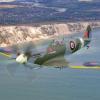
Craigyboy Posted November 23, 2022 Author Share Posted November 23, 2022 3 minutes ago, Bomber_County said: Amazing Craig, glad to see this one close. What a day you must have had at Coningsby. Being only 15 miles at most, in a straight line from BBFM home, I see the old girl most weekends during show season. You're a lucky man. Beautiful lady. She's almost done now then it's onto another BBMF start MkIX Spitfire, the new 1:24 scale 3 Link to comment Share on other sites More sharing options...
Martinnfb Posted November 23, 2022 Share Posted November 23, 2022 Exceptional build Craig, lovely attention to detail. Cheers Martin 1 1 Link to comment Share on other sites More sharing options...
BlrwestSiR Posted November 23, 2022 Share Posted November 23, 2022 Fantastic work on the Lanc. And yes, masks instead of decals almost all the time. Carl 1 1 Link to comment Share on other sites More sharing options...
Craigyboy Posted November 23, 2022 Author Share Posted November 23, 2022 Next up was another of the annoying corrections you've got to make to this kit and it's the formation lights on the rear of each wingtip. On this model they appear as three separate lights protruding from the rear of the wing. They should sit, from all the conflicting reference I've searched through, behind a blue glass cover similar to the green and red nav lights at the front of the wing. (note to self yet again, think long and hard before you hack the wingtip off of a £400 kit). As you can probably see from the photo it's a bit too late as I've started. Problem is I had no clear plastic to fit. Thankfully, the fact it's a blue glass cover meant it could be polished a bit under super clear so I let in a piece of perspex, filed to shape, polished and sprayed Tamiya clear blue and it thankfully came out OK...on both sides! Clear red and green sprayed nav lights and all looks well. Next comes the little matter of the raison d'etre of the whole aircraft, the upkeep mine (not a bomb). HK's mine still has the wooden slatting that Wallis discarded on the final trials as the mine bounced better without it. Rather than fill and sand all that lot, I tried rolling a piece of 1/10000 plastic sheet round to smooth it out and it worked a treat. The seam will be hidden under the aircraft belly when it's installed. Spray with Mr Finishing surfacer then the debate about the finish can start. Some say black, some olive, some red oxide primer. I like red oxide primer as it gives a bit of contrast so that's what I went with. I also think it ties in with the stories of the bombs only being filled with Torpex the morning of the raid and still being warm to the touch in the afternoon. For a bit of contrast and effect, I sprayed with steel then chipping solution before a top coat of Tamiya hull red which is pretty close to oxide red primer. Then a bit of highlighting and some gentle brushing with a soft wet toothbrush and a nice effect of a bit of loss of primer comes through. As for the preparing of the bomb bay to take the upkeep it's a bit of a minefield (no pun intended) The drawings for the cradle aren't very clear the three pieces need to lean against each other. Once you've made up the cradle the instructions give you a placement point up against two small square stops. It's wrong. The diagram below shows the correct placement at two similar stops further toward the nose. The motor for rotating upkeep is hidden away inside the bay but I sprayed it black, drybrushed it and added hydraulic pipes for the hell of it The belt drive assembly got a makeover as well. I originally thought it was a chain mechanism and was going to replace the chain with actual chain. Good job I didn't as the drive was provided by a vee belt. The pulley however needed a groove in it then I can paint the belt tyre rubber and the exposed pulley in a steel colour Perhaps the most contentious issue surrounding Upkeep is the question of fuses and fusing, Why does it matter for the model when it can't be see? Oh believe me it does! Upkeep had two types of fuse, three hydrostatic fuses designed to cause detonation at 30 feet and, here's the elephant in the room, a self destruct fuse to stop it falling into enemy hands. The SD fuse consisted of a rip off pin that, when pulled out of the end of Upkeep, triggered a spark which lit a length of fuse which in turn, after 65 seconds would ignite the charge and explode the mine. All very Heath Robinson but effective. So what's the problem? Well, for many years the belief was that the pin was ripped out as the caliper arm which held upkeep in place sprung open to drop the bomb. All very well and good but, if that was the case, an accidental dropping on the ground (as allegedly happened when a WAAF pulled the release handle by the pilot's seat by mistake) would give 65 seconds to clear the aircraft before ...BOOM! A "safety catch" was needed so the rip off pin remained un-tethered while on the ground meaning an accidental dropping would not rip it out but disengaged just after the aircraft was over enemy territory arming the SD fuse. How that was achieved? A claw fastened to the starboard caliper arm was fastened to a cable running to the cockpit ove the outside of the airframe. This claw could either be open, and not locking onto the rip off pin, or closed and grasping it, Before take off and until over enemy territory, the claw was open. Once over enemy territory, the cable was pulled, closing the claw over the rip off pin and arming the fuse. There;s now evidence for this in this photo of Les Monroe's craft showing the chafing of the cable over the airframe. Also of the pulley the cable ran over before it entered the cockpit. Put it all together and it's starting to take shape. Last tiny iccle thing that's really bugged me since I noticed it is the crew door. I noticed it had a lip on the inside. How could it when it opened INWARDS???? That's gone As ever, thanks for looking. Please feel free to challenge my musings, it's how we all learn after all. Just Exhaust staining and oil and grease and I think I'm almost there. Phew 6 Link to comment Share on other sites More sharing options...
Irishman1 Posted November 24, 2022 Share Posted November 24, 2022 Fantastic job! To me, the investigation into the history and function of the various systems and Options that were implemented like this is one if the most rewarding part of modeling!! 1 Link to comment Share on other sites More sharing options...
Craigyboy Posted November 24, 2022 Author Share Posted November 24, 2022 18 minutes ago, Irishman1 said: Fantastic job! To me, the investigation into the history and function of the various systems and Options that were implemented like this is one if the most rewarding part of modeling!! Me too. Love the research. Square eyes though! 1 Link to comment Share on other sites More sharing options...
crazypoet Posted November 25, 2022 Share Posted November 25, 2022 I’m *loving* this! Following happily 💯 1 1 Link to comment Share on other sites More sharing options...
Craigyboy Posted November 30, 2022 Author Share Posted November 30, 2022 Last leg now. I added the trailing aerial weighted end made of biro ball bearings dipped one at a time into CA and formed into a string. The static between them is a nightmare though. Exhaust staining next. There are many and varied patterns but some things seem constant across most aircraft. The outer engines only get white lead deposits on one side Undersides are quite white The exhaust shrouds have some consistent patterns and, frequently, a white cone of lead I didn't want too heavy weathering so worked from images such as these: So. for better or worse, here's what I came up with. This is a bit of a montage with the wings partly on. I took these now as I won't fix the wings on properly until it's ready to be collected, simply as I'd be too scared to take them off again now and I've nowhere tp store it with the wings on it's too flippin' big. Aerials wise, as you'll see in the pics, I've added both fin to cockpit ones although I think the port side one was only used if an extra R1155 receiver was positioned at the navigator's station. The long Gee MkI whip aerial protrudes from the canopy near the DF loop and I've added the VHF aerial shown on Gibson's Lanc front starboard in the nose. The other two are Standard Beam Approach (forward top of fuselage ) and the rear whip aerial is the TR1196 designed for air to air and air to ground communication. Trouble was, it wasn't much cop for air to air which is why the dams planes had the VHF systems fitted. So just a bit of oil and grease to add and a diorama base to build and she's done. Attempted reproduction of the iconic shot of Gibson's Lanc although in that one the wooden slatting around the mine is still present which points at the photo being taken while training. 9 Link to comment Share on other sites More sharing options...
BlrwestSiR Posted November 30, 2022 Share Posted November 30, 2022 Wow, that looks stunning. Great job on a fantastic model. Carl 2 1 Link to comment Share on other sites More sharing options...

Recommended Posts
Create an account or sign in to comment
You need to be a member in order to leave a comment
Create an account
Sign up for a new account in our community. It's easy!
Register a new accountSign in
Already have an account? Sign in here.
Sign In Now