DocRob
-
Posts
7,127 -
Joined
-
Last visited
Content Type
Profiles
Forums
Events
Gallery
Everything posted by DocRob
-
Revell 1/32 Spitfire Mk IIa
DocRob replied to Peterpools's topic in LSM 1/35 and Larger Work In Progress
Looks great Peter, but what a shame about the cockpit fit. Can't be so difficult to get that right. I'm not an expert with Spitfires, but the airframe looks about right. I have some Revell kits in stash, but never built one after my twens. Cheers Rob -
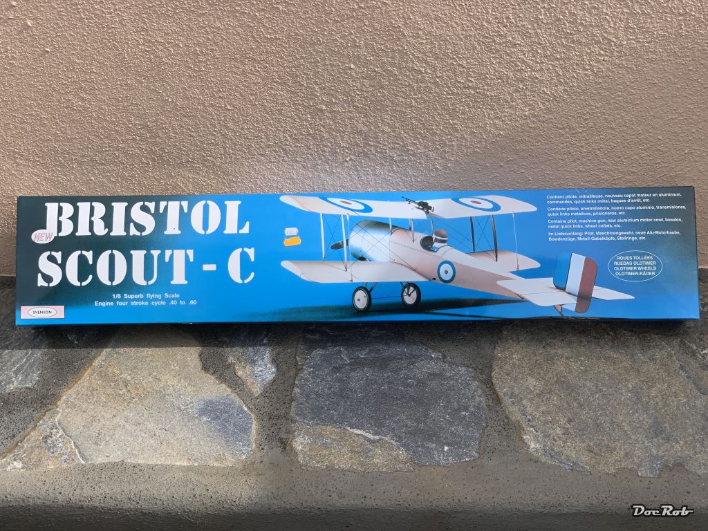
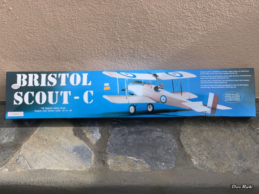
I will definitely get me one to have a smaller brother for my huge wooden Scout-C, I recently bought. To have a 1/32 3D model for detailing the big bird is a great plus . Cheers Rob
-
No problem with that Mike, we are here to learn, and I haven't heard of that kind of behavior before, you mentioned with copper wire. I worked a lot with copper tin when I was younger, but never experienced this effect. Cheers Rob
- 329 replies
-
- 2
-

-
- uss arizona
- eduard
- (and 1 more)
-
Well Peter, yes and no to your conclusions. The first part is correct, no water is needed for cooling down the parts. Harden metals is a different case, to my knowledge it works only with metals including carbon like steel. Hardening needs higher temperatures, depending the metal. When you want to fabricate a tool from steel, let's say a knife, you harden the blade first with high temperature and cool it instantly in oil or water. The blade will be ultra hard then (good), but brittle as glass (bad). Depending on the purpose for the blade, it will be annealed in the next step, to soften the blade to the right balance between hardness and flexibility. I only mentioned hardening, because these two heat treatments belong together. Maybe I should have left the hardening out, because it doesn't apply to non ferrous metals like brass. Non ferrous metals can have inner strains as well and these can be lessened through annealing. Cheers Rob
- 329 replies
-
- 2
-
-
- uss arizona
- eduard
- (and 1 more)
-
Thanks Gary, you don't need to start though, the GK isn't finished, am I right? Cheers Rob
- 329 replies
-
- 2
-
-
- uss arizona
- eduard
- (and 1 more)
-
Thank you Peter, I got a bit of a brass flash lately . With metals there are generally two processes for altering the crystalline structure to achieve the wanted material characteristics. There is hardening, where you heat up the metal to a defined degree and then cool it more or less rapidly down with air, water, oil, whatever. The cooling process strains the crystalline lattice structure immediately and the result is a very hard version of your base material, which are mostly carbon based steels. Annealing is the process to release a defined amount of strain due to inducing a lower heat than with hardening. the crystalline grid relaxes a bit, so to say. Every metal has a different set of annealing colors, which develop with the heating and show the temperature to which the material was heated. you can study that on steel exhaust manifolds, where you often got a full rainbow of colors, each indicate a different temperature and if you know, which material was used, there are tables, which give you the exact amount of degrees Fahrenheit or Celsius. Brass is not hardened, but has structural strains resulting from the production process and annealing orders the inner grid of the material and as a result softens it. You don't need to pour cold water on the part, it's only about reaching the appropriate temperature. I hope my blah is understandable in English, it's not so easy to sum up complicated processes and figure for the right words. Cheers Rob
- 329 replies
-
- 4
-
-
- uss arizona
- eduard
- (and 1 more)
-
Sorry to hear about your situation, Harv. Being separated after such a long time is quite a change. Go slow and see the positives, maybe the way, some of the other guys mentioned, maybe in other ways. I wish you luck with the move and hope to see some building output, no pressure applied . Cheers Rob
-
Nice progress with the super smooth sub, Scott. I think it's a good idea to display it only with an ocean floor scenery. If you would use clear resin, it wouldn't be ready through the GB's deadline, as you only be able to cast it in 1 cm layers, to prevent bubbles and heat build up. Cheers Rob
-
Great display, love the water effects and general setting, as well as the low budget, but effective trees. I wonder how the heat build up happened with the clear resin. I only worked once with the stuff, a 2K resin, which worked fine and the manual said, never to build up layers of more than a centimeter, but yours is shallow, strange. Cheers Rob
-
Thank you Mike. Annealing alters the crystalline structure inside a metal due to applying a defined amount of heat. I use a candle and hold the parts a bit over the tip of the flame, until it changes into a blue color, then I move the part, let the blue wander with the heat, until the part is finished. If you hold it with tweezers or clamps, you have to change position and anneal the clamped section as well. The clamp, tweezer or pliers take the heat and hinder the annealing process. Don't glow the parts, they might receive structural damage, when you do. Sounds complicated, but really isn't and helps a lot, when it comes to bend curves. The brass is less springy after annealing and softer as well. For that reason, I anneal only curved parts, to not loose structural strength. Cheers Rob
- 329 replies
-
- 3
-
-

-
- uss arizona
- eduard
- (and 1 more)
-
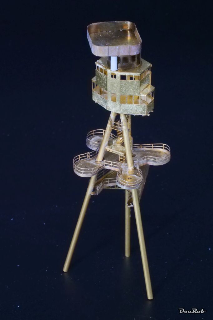
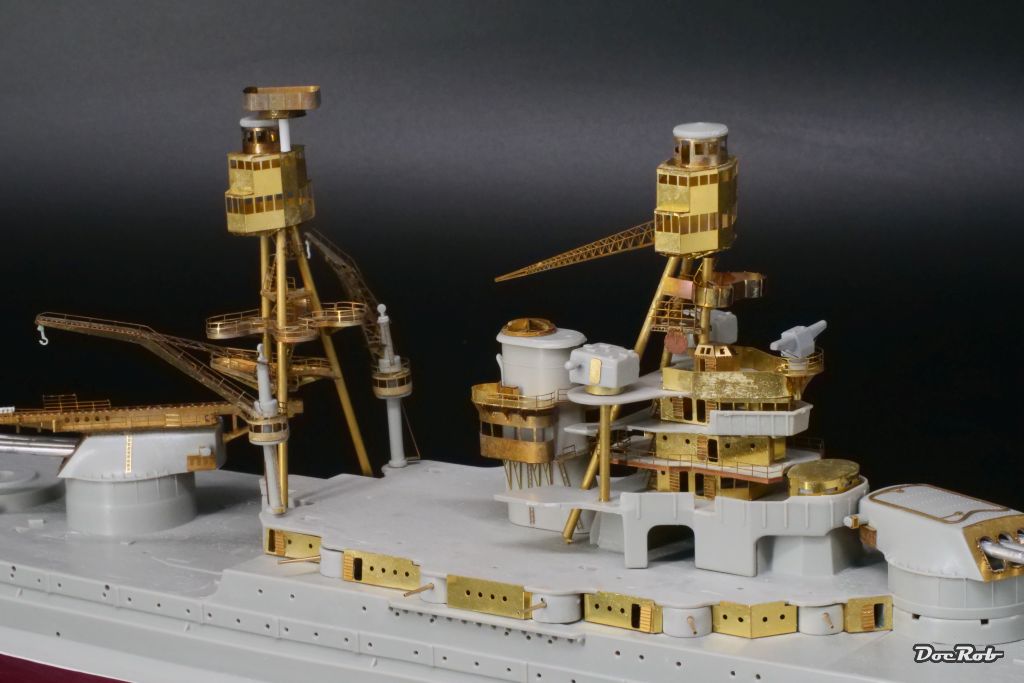
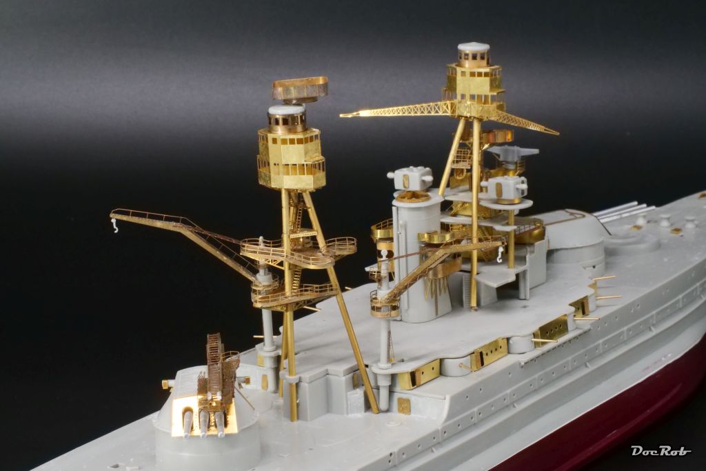
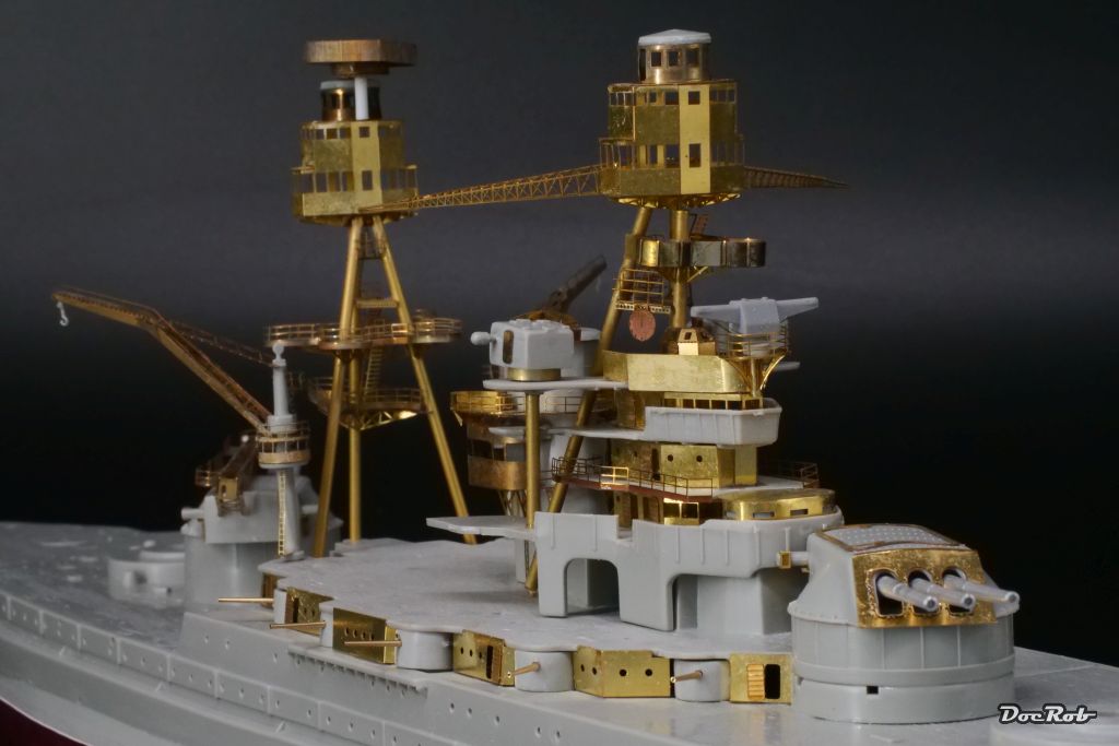
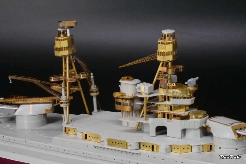
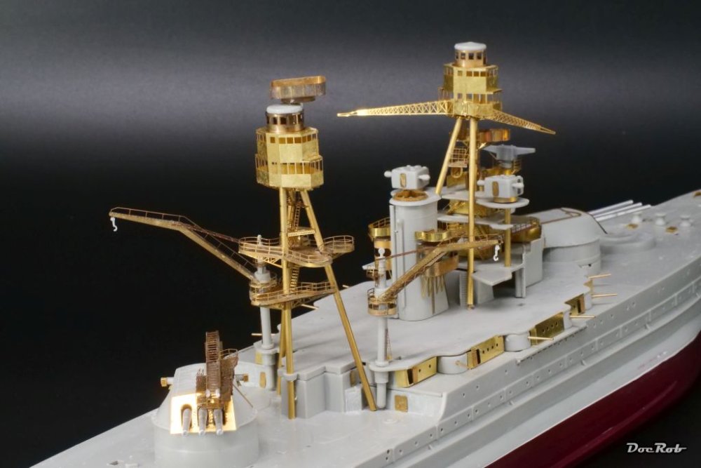
The aft mast section took me three days to get there. First the basic construction, than the traverses and finally the railings, which were very complicated to form, following the shape of the masts decks. Without annealing, I couldn't have done it. Half a liter of CA later, the tower construction misses only some antennas, the searchlights and AA-guns and some other minor details, which I will add later. The entire midship section starts to look busy now. There is not that much plastic left and there is more PE to come, along with the boats, davits,... Cheers Rob
- 329 replies
-
- 9
-
-
-
- uss arizona
- eduard
- (and 1 more)
-
Hi Phil, the manual from Eduard is not bad. It mostly shows what plastic has to be removed (a lot) and the placement of the PE is shown mostly correct. There are some detailed plans for the complicated mast construction with a measured side view, that helped a lot. Where the manual lacks, is sequence, which is not overly logical and in case of subassemblies there is non given, you have to figure out the building sequence yourself. As you have to plan the building steps ahead properly, that's not so hard to come by. It seems that your equipment needs a proper update, what will happen, when you run out of masking tape and can't open the lid. My good old Rega Planet CD-player has decent sound quality and no resonance problems with a lid as it has none. You have to manually open the starship Enterprise shaped opening, and put in the CD, no levers no nada. It's like many Rega products a non nonsense product, but a bit unusual. I don't hear Cd's that often and therefore will stay for another while in my rack You say something about good sounding music. It's so nice to hear all the bells and whistles. I don't own too many classic recordings and the Gorecki Sinfonie #3 is on my search list, sung by Beth Gibbons from Portishead. Cheers Rob
- 329 replies
-
- 2
-
-
- uss arizona
- eduard
- (and 1 more)
-
Revell 1/32 Spitfire Mk IIa
DocRob replied to Peterpools's topic in LSM 1/35 and Larger Work In Progress
The pit looks fantastic, Peter. Quinta sets are great, but it needs a knowing hand to integrate them that well. Cheers Rob -
"Pasture" F4U-4 finished
DocRob replied to JohnB's topic in LSM 1/32 and Larger Aircraft Ready for Inspection
Indeed, one pic is better than thousand words . Cheers Rob -
Should be a good start, low part count, only some bits and pieces in PE, but the casting quality is not on par with the Japanese offerings. I built the Fokker D. VIII from Mikro Mir and it needed a bit of scratch building and improvisation. Cheers Rob
- 329 replies
-
- 4
-
-
-
- uss arizona
- eduard
- (and 1 more)
-
Thank you Kevin, hmm, well, ships, yes, I will build others, but I like to do different things. There are so many nice kits in my stash, so many projects in my head. The next will be a ship too, I will rig my wooden sailing ship, the Duchess of Kingston. Cheers Rob
- 329 replies
-
- 2
-
-
- uss arizona
- eduard
- (and 1 more)
-
So far, I haven't lost a part Peter, that equals the loss of the complete PE-set, that I can't find anymore, for the originally planned Schnellboot build . Cheers Rob
- 329 replies
-
- 2
-
-
-
- uss arizona
- eduard
- (and 1 more)
-
"Pasture" F4U-4 finished
DocRob replied to JohnB's topic in LSM 1/32 and Larger Aircraft Ready for Inspection
Fantastic and different looking Corsair John. I love the huge contrast on that bird, makes it look special. Somebody here mentioned during my Corsair build, that the wings fold only simultaneously and not single sided, don't know if that is true. Cheers Rob -
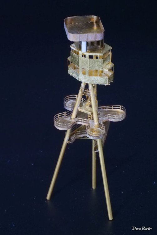
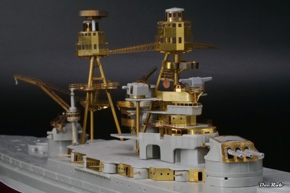
Thank you Peter, the mast assembly sans flying bridge is seven centimeters high, really not that large. The CA causes white residues which look very ugly and the annealed parts, well look dark and dirty. Nothing a coat of primer couldn't cover. But before, I have to install all the railings and ladders to this section, but this is for another day. Cheers Rob
- 329 replies
-
- 3
-
-
- uss arizona
- eduard
- (and 1 more)
-
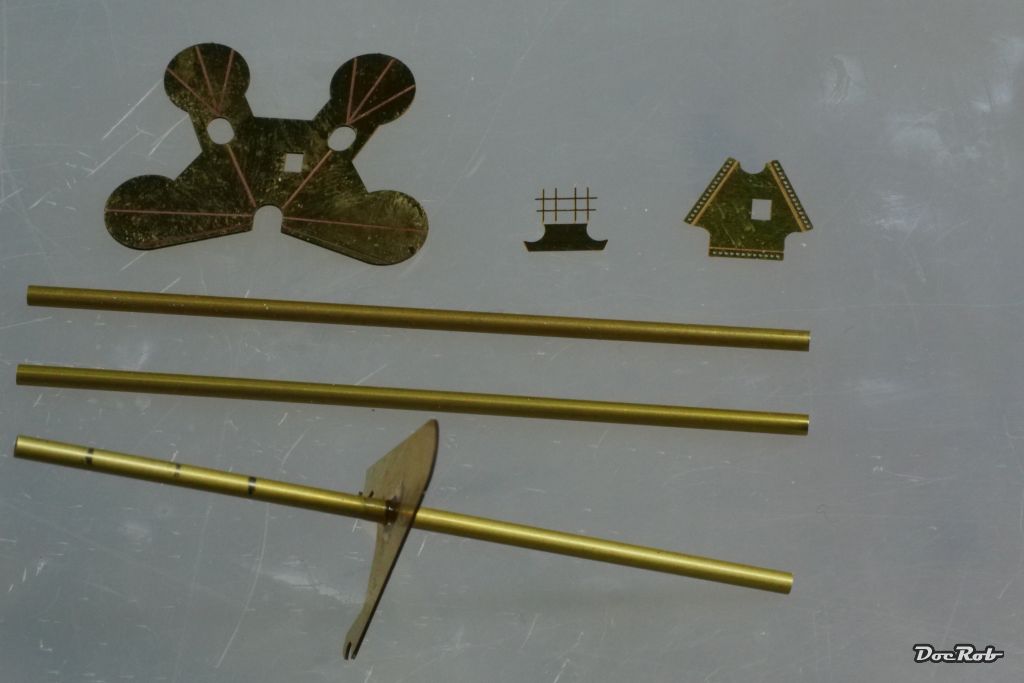
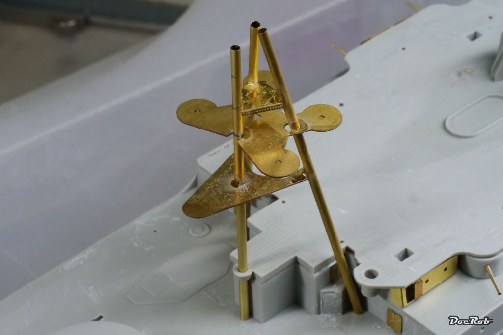
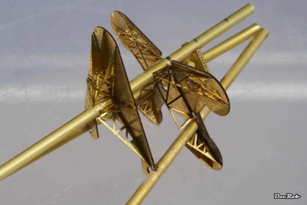
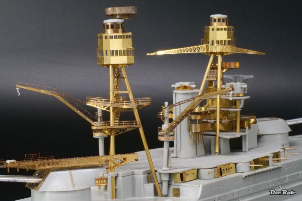
More PE-madness was on todays schedule. I wanted to finish the basic construction of the back masts and flying bridge. First was creating the masts, using 2 mm brass tube cut to length like mentioned in the manual. Luckily the manual contains a precise drawing of this subassembly with measurements added. The single aft mast was used to mark the height of the different decks with a pencil and then glue on the first deck, using a steel angle for orientation. Then I added the two decks above with just a drop of CA and put the assembly in it's designated place on the deck and added the other two masts. I tried to do this step as quick as possible, to have some wiggling time, before the CA cured. Later, all was secured with more CA . After all was aligned and the CA had hardened, I added all the traverses to the decks undersides, leaving a very delicate construction. The flying bridge was bent and the circular or rounded parts got bent using a rubber mat and some steel rod, after annealing the brass. Not all looks totally clean after the CA mess, but keep in mind, these pics are heavily macroed and everything will hopefully look proper under primer and paint. Cheers Rob


- 329 replies
-
- 12
-
-
-
- uss arizona
- eduard
- (and 1 more)
-
Thanks for showing Gary, I don't mind having pics of other builds in my log. You never know, what comes of it. Your GK looks absolutely great and these holes for the secondary artillery only show, when heavily macroed. You definitely have a point in assuming a historical scenery and make the ship fit accurately. You have to do a lot of research to get everything right. With the Arizona, I'm absolutely no expert and I will not dig too deep into reference material. With such a well known subject, I'm in the minefield with my approach, but if it looks Arizona in the end, I'm ok with that. The water base looks great and adds a lot of 'real feel'. I will decide later, if I go this route. Figures are planned for the USS Arizona. I have a set of sailors made by Ion, which look really good. Cheers Rob
- 329 replies
-
- 4
-
-
- uss arizona
- eduard
- (and 1 more)
-
Thank you Peter and Mike, you should have seen the original plastic . They were some of the worst kit parts, I've ever seen. Cheers Rob
- 329 replies
-
- 3
-
-
- uss arizona
- eduard
- (and 1 more)
-
ProModeler 1/48 PBY-5A Catalina + Goodies, RFI
DocRob replied to CANicoll's topic in Let’s Get Wet Group Build.
Wow, you did marvels with these pilots Chris, they do look very natural in their poses and are painted very convincingly. Cheers Rob -
Congratulations Peter, you not only finished first, but in quality and style as well. Your Arizona bound birdie will be one of the more colorful contributions to the GB and I have to say, it's very high up the wow-meter. You took that good ole' kit and made it look special. My contribution, the platform for yours will take a while longer to be finished . Cheers Rob
-
My Albatros B.II is on it's way too Bill. Thanks again for your generous offer. I had a Dolphin on Backorder as well, but skipped it. I have too many British fighters in my stash. I bought some sheets of Aviatic linen decals instead, for the Albatros and other projects. I have the early Halberstadt here, which will receive a very complicated paint scheme. Cheers Rob