DocRob
-
Posts
7,048 -
Joined
-
Last visited
Content Type
Profiles
Forums
Events
Gallery
Everything posted by DocRob
-
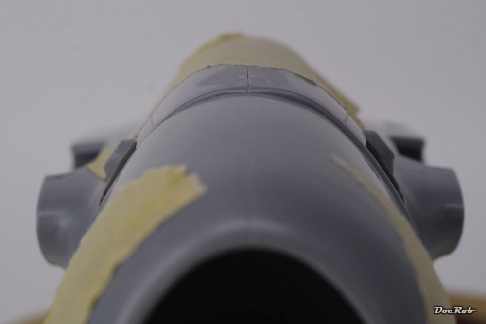
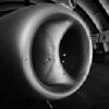
Thank you gentlemen, by the way, looking for the right color for the inside of the cowlings, I watched some pictures and found a great variety of colors. Some are natural metal /aluminum, some light grey and others interior yellow. Which could be probably right for the Dottie Mae? Studying the pictures, I tend to NMF. @ Bill, I read about that method too and considered it, but the upper shape of the cowling fuselage joint seems correct to my eye and by lowering the engine mount / cowlings by a millimeter the gap between the cooling flaps of the cowling and the fuselage doesn't look right, the space between these flaps and the fuselage will get uneven. This upper joint is very visible and to me had priority to maintain. And my method of reshaping the bottom of the fuselage by grinding a little and rescribe these two panel lines took ten minutes and what was more important to me corrected the right part, the fuselage, as I think the engine / cowlings are more or less right. It's hard to tell but I think on your second photo, the lower fuselage looks a little flat to me, there should be a little 'belly', like on the photo of the original Jug. Cheers Rob
-
Thanks Gus, and you are probably right about the amount of shape issues when there are different complex 3D curved objects involved. It must be a not so easy job to get everything right, but at least the Hasegawa plastic looks like a Jug with only some minor issues to my uneducated eye. Thanks John, after the struggles which kept me from finishing the Me-163, this is a real pleasure build. Everything is relaxed and easy, fit is good and the engineering is as well. Sometimes it just feels great to enjoy building a kit, instead of a permanent fight while doing so. The last word about the Komet is not spoken yet, because I hate to quit. It just doesn't feel good to be beaten by a chunk of plastic . Cheers Rob
-
 Looking good, it seems like the ejector pin nightmare ended and you can concentrate on the kit now. Like the plumbing in the cockpit. Cheers Rob
 -
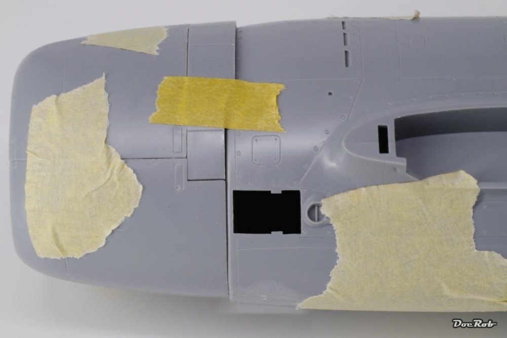
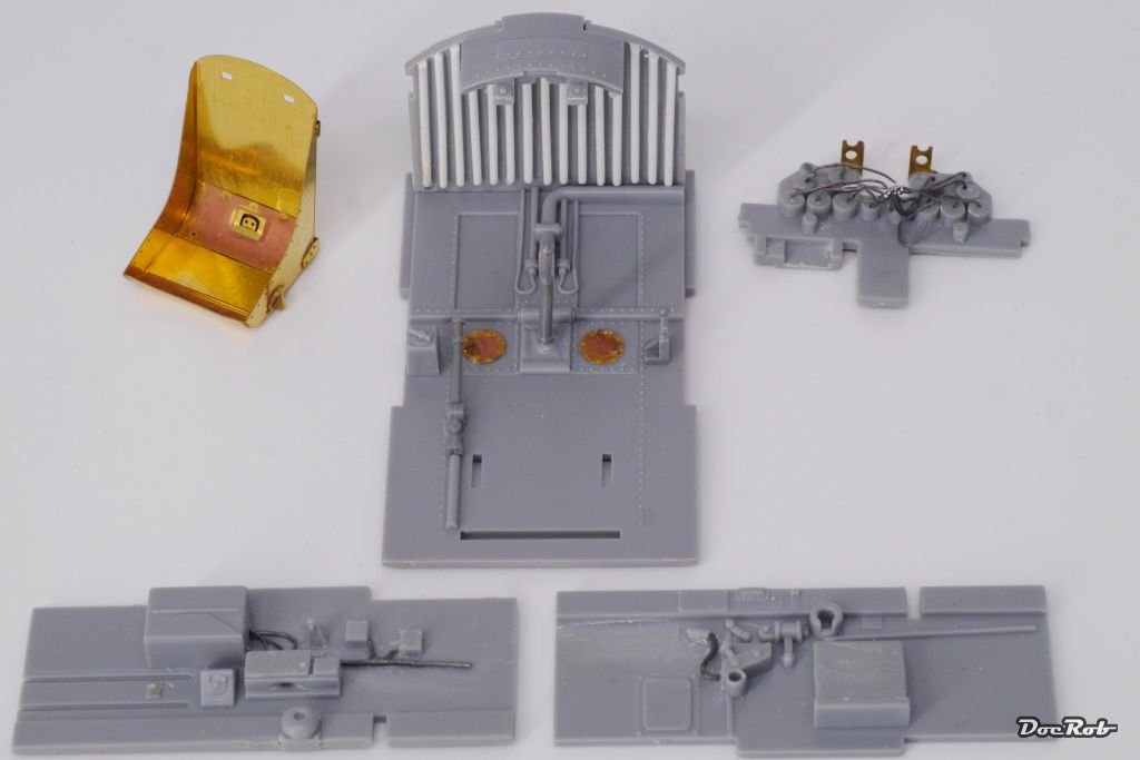
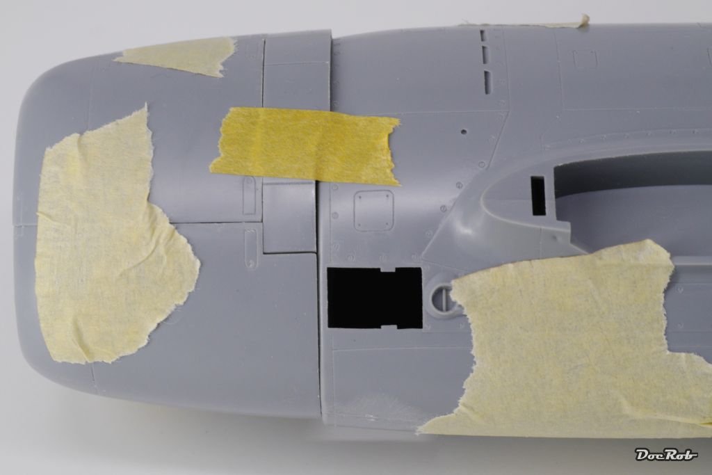
Hola lovers of the flying heavy metal, certain members in this place made my mouth watering with their inspiring builds of P-47's recently. I always liked the brutish shape of a Jug combined with a certain kind of elegance, which to my eye is the result of a well engineered design, not to mention the shiny appearance of the natural metal finish. After my stalled build of the captured Me-163 Comet, I had to choose a subject where the fuselage was not a matter of thousand parts to align, it had to be a KIS a keep it simple design a halved fuselage. That's how the Eduard P-47D limited edition ended it's shelf live. I will not bore you with an in deep WIP, but will just show bigger steps and wanted or necessary modifications to the kit and will emphasis the natural metal finish, which is a first to me, at least in 1/32. First steps were to cut and sand all the parts needed for the cockpit, engine, wheels, flaps and test fit and plan the build. Construction started with the cockpit which is nicely rendered in plastic, added with a hefty dose of PE. It's a simple construction and is done in a whiff. For enhancement, I drilled out the visible back side of the instruments with a 0,4 mm drill and added lead wire with a diameter of 0,3 mm into the holes and fixed everything with a tiny drop of CA. I never wired a kit before and because it is easily done I will do more of this in other builds and possibly with the engine too, where PE ignition wires are provided, which I may substitute with lead wires. I also added some small styrene strips to the front firewall of the cockpit to represent the corrugated metal, which was used there. After test-fitting the fuselage and cowlings, I didn't like the representation of the lower shape between these parts. There was a visible step which does not correspondent with the real thing. After sanding the lower part of the fuselage and rescribing two panel lines I was satisfied with the result. It's a ten minute fix and worth it. Now everything looks a little bit more like a real Jug. While watching this photo, I think I might sharpen the edges of the movable cooling flaps a little, if it doesn't give to much insight into the nothing of the backside of the engine. Cheers Rob


-
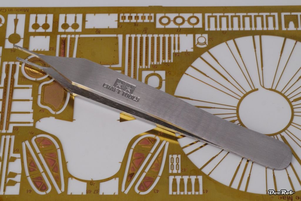
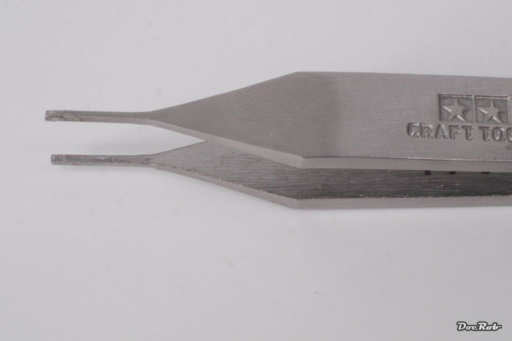
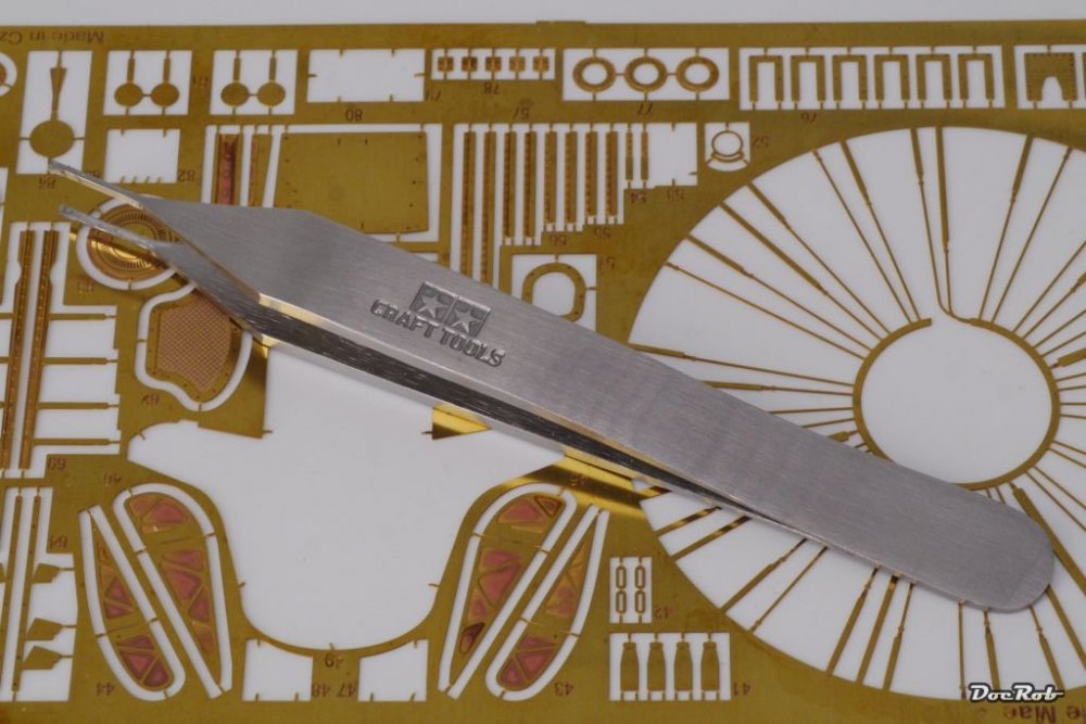
Buenos Dias, friends of the tool heavy workbench, I have a very special relationship towards photoetched parts in modelling. I love to work with metal, enjoy the enhancement of detail and after applying PE sometimes I whish, it would not be necessary to paint these parts because of the luster shine. On the other hand PE can be a real PITA and has the tendency to unify itself with the carpet monster even more than plastic parts. Over the years I used lots of tools for working with PE, there were bending tools, rolling tools, pliers and tweezers and all of them were helpful, but there was something missing between the pliers and a fine tweezer and then I bought this little gem. It is the Tamiya Bending Tweezers (for Photo-Etched Parts) with the Item No: 74117. I got it six weeks ago and I absolutely love that tool. It has become a nearly universal tool for small PE parts. Because of it's short tweezer tips which are finely grinded with sharp angles you can apply enough force to hold PE-parts in place and bend them around the edges. The smallness of the tips make it easy to bend complicated three-dimensonal forms. Another advantage is, that with mentioned small PE parts, there is a much reduced need for tool changes, because of the versatile design. I highly recommend this little helper. It improved my enthusiasm with small PE parts a lot, because of the easiness of use and it's versatility. Tools should make live easier and this one is a very fine example. Cheers Rob

- 10 replies
-
- 11
-

-
A Wee Side Project: the Airfix Car Door Tiffie
DocRob replied to Uncarina's topic in LSM 1/35 and Larger Work In Progress
Looking superb and your way of applying the paint a little patchy supports the stressed surface effect in a beautiful way. Cheers Rob -
Whoa, that's 1:1 scale and an amazing level of detail. Weathering could be improved with some oils . Cheers Rob
-
But then you should go the extra mile and use ALT-whatever for the "ü" in Grünherz and get rid of the 't' . Yeah I know xxxxing Germans . Cheers Rob
-
1/18 P51C Mustang "Lopes Hope 3rd"
DocRob replied to airscale's topic in LSM 1/35 and Larger Work In Progress
Amazing attention to detail, with a little afterthought I might tell you the size of the pilots boots by the scratch marks . Cheers Rob -
Yes, I live in the Islas Canarias, why? Cheers Rob
-
Nice pit, Grunhertz and a lot of the fine work will be seen, because of the big glasshouse. Cheers Rob
-
Hi Peter, after using the Havox box for more than a year now, I have to say, I'm still satisfied with it. The only upgrade I should have made is the purchase of two extra light panels, which was not available by the time I bought the box and now the big A is not sending the extra panels to my tiny island. Cheers Rob
-
1/48 Wellington Mk.X (He727 NA-K)
DocRob replied to JeroenPeters's topic in LSM 1/35 and Larger Work In Progress
You are a brave man Jeroen, manipulating canopies gives me the creeps. Cheers Rob- 304 replies
-
- 3
-
-
- wilnis crash
- trumpeter
- (and 1 more)
-
Once, back in Germany I bought a Toyota and tried to understand the function of the air conditioner by reading the manual. It was impossible to understand the function and how to's, but was a lot of fun anyway. You wouldn't have thought about what is possible in German language . Looking at the real thing, everything was clear in a second, because it was well engineered. Sometimes I fear that the same people write the manuals to weapon systems . Cheers Rob
-
Nice and colorful rendition of the workplace. I love the red PAC-Man-Screen . Cheers Rob
-
Hi John, my brain didn't fool me with this one. There was a recent build here by BarryWilliams. https://forum.largescalemodeller.com/topic/5328-faa-corsair-ii/?tab=comments#comment-67325 Cheers Rob
-
That's what will flatten out the squirrel poulation, eh? Cheers Rob
- 2,035 replies
-
- 3
-
-
- car related stuff
- anything about cars
- (and 6 more)
-
Eduard P-47D Thunderbolt "Dottie Mae" WIP
DocRob replied to a topic in LSM 1/35 and Larger Work In Progress
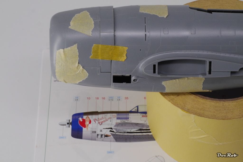
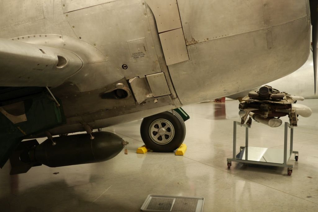
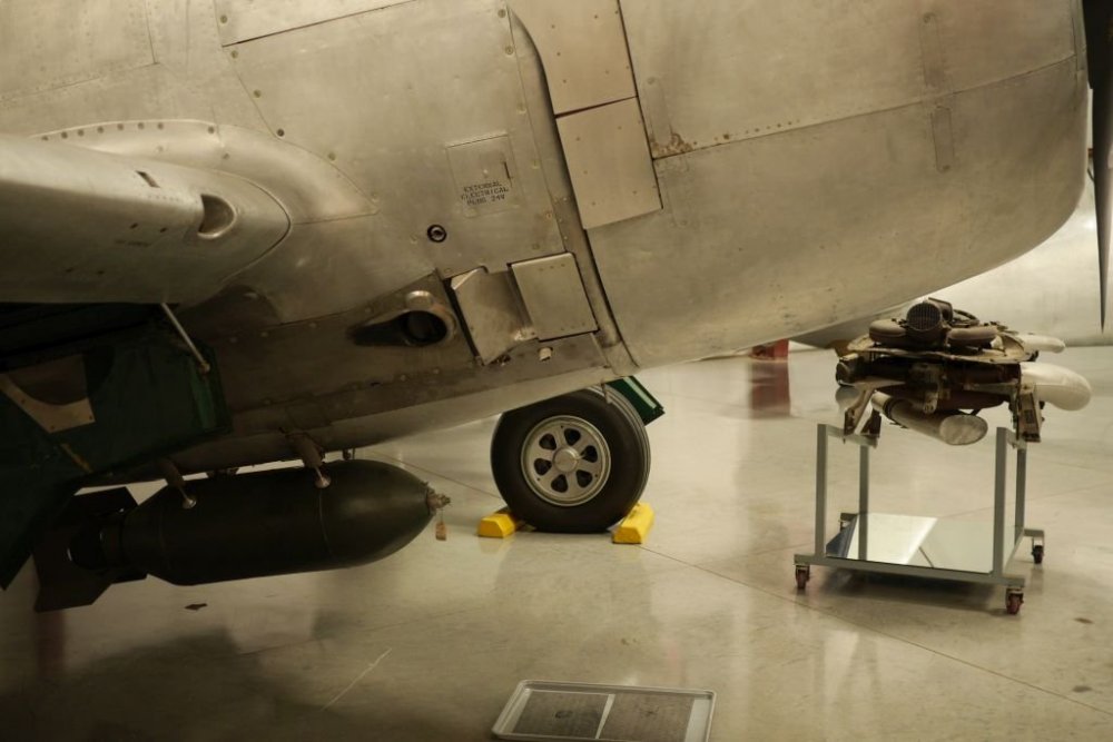
I tried the sanding the bottom fuselage and rescribe two panel lines method and for me that solution is sufficent. There still is a little bulge in the lower fuselage, but that is to be seen on the side drawing and on the photo of the Chino P-47 below as well. The correction job took just ten minutes. So for now I stop self WIP-ing your WIP Danny (till further questions arise) . Cheers Rob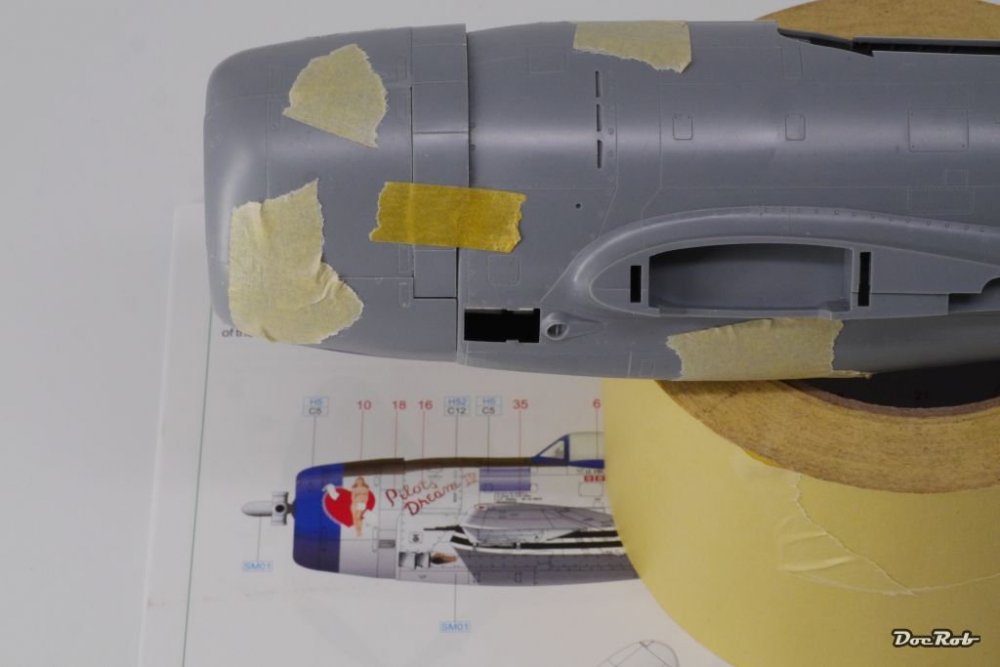

-
Kitty Hawk F-5F done.
DocRob replied to Clunkmeister's topic in LSM 1/35 and Larger Work In Progress
Nice Ernie, but sometimes 15 seconds are enough for the glue tu cure I got headaches because of all that speed issues. Cheers Rob -
Since there is no photo etch involved you gonna etch a little on the inside , just joking, love the stuff too, but prefer a good old Elijah Craig. Anyway the stuff keeps you from trembling while you master the fine and delicate ZM ingredients . Cheers Rob
-
Double applause this time , first for a beautiful built and painted bird and second because of the unique way you displayed the Hawk, chapeau. Cheers Rob
-
Nah, it's off scale . Nice haul Danny, will you display the Lightning with the helmet? Cheers Rob
-
1/48 Wellington Mk.X (He727 NA-K)
DocRob replied to JeroenPeters's topic in LSM 1/35 and Larger Work In Progress
Wow, great job on the bomb bays. Never thought about that there are so many doors involved, but it pays, the inner structure is still visible. The shades of black look bueno too. Cheers Rob- 304 replies
-
- 3
-
-
- wilnis crash
- trumpeter
- (and 1 more)
-
Eduard P-47D Thunderbolt "Dottie Mae" WIP
DocRob replied to a topic in LSM 1/35 and Larger Work In Progress
Thanks Danny, that's what I had in mind you did. It's hard to tell from your recent pictures, but by lowering the engine/cowling, it seems to me that you loose the correct shape on the upper side of the cowling/fuselage joint. There should be a little step and this to me is more important to keep, as it is very visible. A perfect solution would be, lowering only the lower part of the cowling by a millimeter and fill the gap with some sheet., but I might give the above mentioned method of sanding the lower fuselage side the preference. Thanx for brainstorming mate and I hope you don't mind me hijacking your thread about your wonderful Dottie Mae. Cheers Rob -
Eduard P-47D Thunderbolt "Dottie Mae" WIP
DocRob replied to a topic in LSM 1/35 and Larger Work In Progress
Hi Danny, watching your great Dottie Mae developing, made me starting mine as a relax build, before going back to the dreadful Komet. So far everything is looking bueno and I have to say, that I really enjoy a kit with two fuselage halves instead of these multiple panel affairs . While dry fitting one question arose and because your pics of the engine/cowling surgery dosen't show anymore I ask you directly. The 1mm step on the bottom connection of the cowling/fuselage connection is visible on my kit too (who wonders). How did you manage to lower the engine mount and keep the upper shape of the engine cooling flaps (much more noticeable) in shape. I'm thinking about thinning the fuselage a little on the lower side behind the cowling, instead of lowering the engine mount. There are only a few panel lines to rescribe. What do you think? Cheers Rob P.S. The step looks worse on the pictures than in reality, it's maximum is 1mm, in the middle only half a millimeter.