BlrwestSiR
-
Posts
9,173 -
Joined
-
Last visited
Content Type
Profiles
Forums
Events
Gallery
Everything posted by BlrwestSiR
-
That is one big pair of glasses. Absolutely stunning diorama.
-
A very detailed 1/12 car model of the Jaguar that raced at LeMans in the early '90s. Multi-media kit so resin, white metal, machined aluminum, PE, rubber and vac parts.
-
Revell 1/32 Spitfire Mk IIa
BlrwestSiR replied to Peterpools's topic in LSM 1/35 and Larger Work In Progress
Nice work Peter. The main seams all look good overall. The glass looks fine and the sprue attachment point isn't as bad as the one on Tamiya's 1/32 F-4 kits. Can't wait to see what it looks like under a coat of paint. As for the Barracuda bits, I wonder if Roy has several moulds that he uses and some may have shrunk/degraded. I have two of the Tempest nose corrections and one is way off dimensionally while the other is almost a perfect match to the fuselage. -
Here's the link to the how-to I did.
-
Back to our regularly scheduled program….
BlrwestSiR replied to ScottsGT's topic in General Discussion
Nice! Our house is way too small for a man cave. I'm lucky to have the space I do in the basement. Great collection of diecasts too. -
Very, very jealous. Nobody around here has them much less second for cheaper.
-
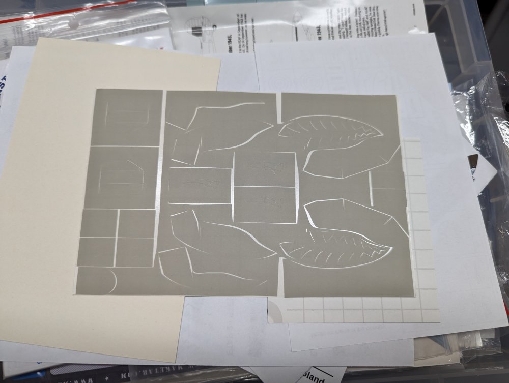
I've used lots of Montex masks and they generally have worked very well and I've gotten great results with them. Masks are my preferred way to do markings in 1/32, especially things like roundels and large codes. I think I posted a how-to on here. If you have any questions about how to do them, just ask. This is my Tamiya Mossie with painted on roundels and fin flash. Code letters weren't available at the time so I had to use decals for those. One thing though. Like all masks made from vinyl, they can deform with age. Mostly due to shrinkage after cutting. Here's a set of Montex masks for the Trumpeter P-40. I bought them for the Hobby craft boxing of the kit so they're fairly old, probably about 10 years. I can probably make these work if I take my time to line things up carefully but they won't always fit together perfectly. Carl
-
An interesting night here last night…
BlrwestSiR replied to Clunkmeister's topic in General Discussion
We ended up with thunder snow and I got to watch lightning and thunder as the snow came down. Definitely an interesting phenomenon. There's about 15cm of snow so only about half the worst case estimate they gave in the forecast. Time to dig out. -
I've got a hair dryer relegated to my bench thanks to the handle being held together with tape. That's what I thought you had as well.
-
An interesting night here last night…
BlrwestSiR replied to Clunkmeister's topic in General Discussion
Glad to hear you're both okay. The same storm is due to hit us any moment now and drop 10-30 cm of fluffy white stuff on us. -
Nice start John. I'm a bit surprised about the gunsight and that ICM missed it considering they did so many new parts for this variant.
-
Peter, don't forget Mark is in Europe so what he has may not be available in North America. Home Depot in Canada has LEDs where you can adjust the wavelength from 3K to 6k depending on the use. I imagine they should have those in the US as well. I'm using a pair of 48" work lights over my bench I got from Costco. They give off way more light than I used to have and were fairly inexpensive too.
-
ProModeler 1/48 PBY-5A Catalina + Goodies, RFI
BlrwestSiR replied to CANicoll's topic in Let’s Get Wet Group Build.
The Catalina is progressing along nicely Chris. If I recall, the main wing is a fairly solid fit and I didn't have any alignment issues with it. For the tailplanes, it may be a good idea to run a brass rod and pin them to get a more solid mount. Revell did a boxing of Cousteau's PBY in 1/72 along with his Calypso. -
Considering ZM Bf-109 for next build.......
BlrwestSiR replied to JohnB's topic in Modelling Discussion
Been wanting to see a Counter Invader build so this will be one to follow. Carl -
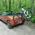
A friend has a Series III 110 pickup. The ride was always incredibly stiff. One time a bunch of us went mountain biking and when we were done we all piled into his truck at the trailhead. 8 of us and our bikes crammed in. As we drove down the trail road, my friend commented that the Defender had never ridden so smoothly before due to us all loaded in there. Meantime my colleague's husband traded in one of the last Canadian Defender 90s sold here for the new one. I didn't say anything but that was a trade down in my eyes.
- 2,036 replies
-
- 3
-

-
- car related stuff
- anything about cars
- (and 6 more)
-
British colors Extra dark sea gray and Sky
BlrwestSiR replied to ScottsGT's topic in Modelling Discussion
It's easy at the LHS near my work. I'd say more than 2/3 of the shop is dedicated to paint, tools and supplies with just the front section containing kits. Their Gunze section is almost a full aisle 15 ft long. -
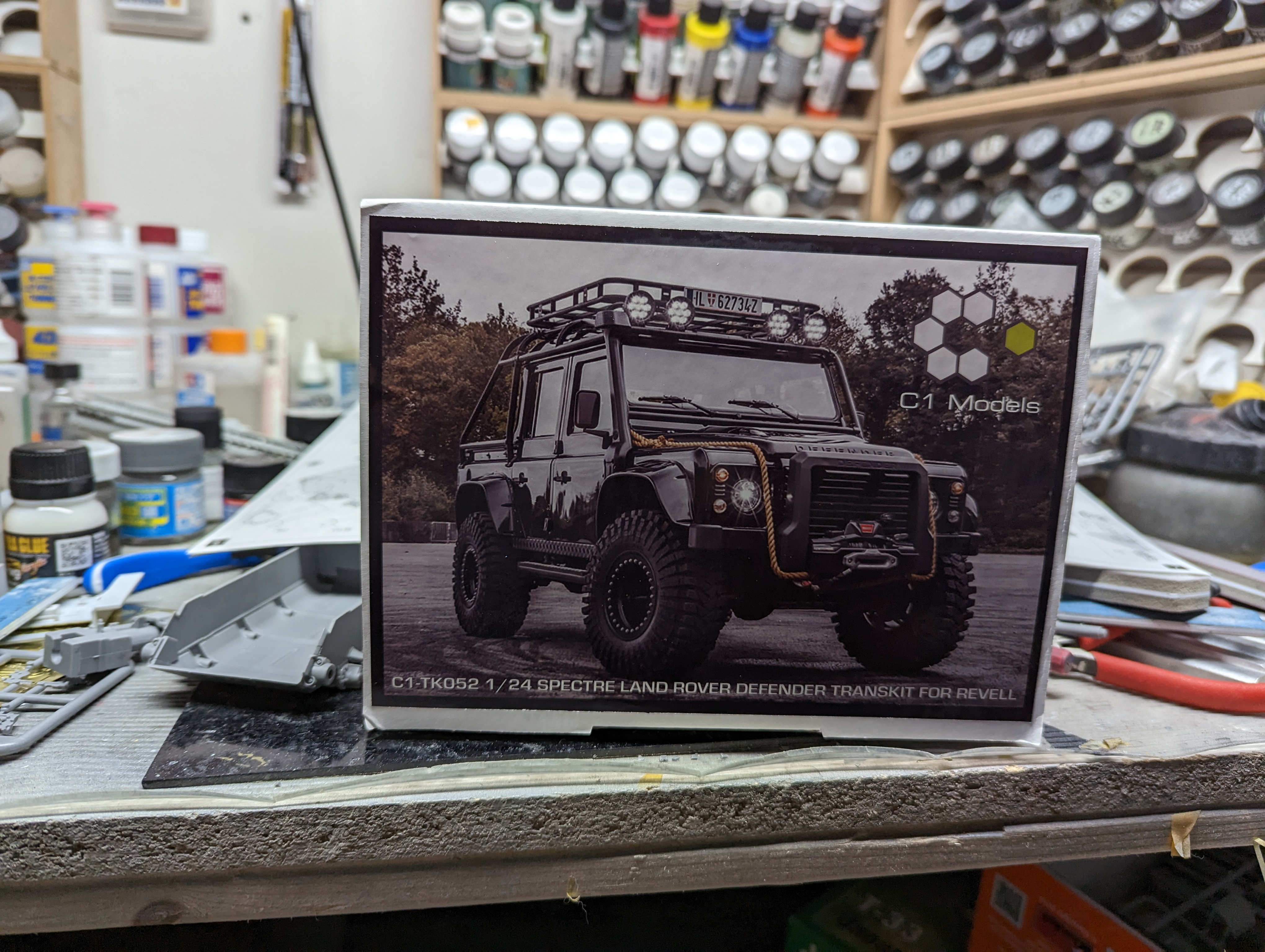
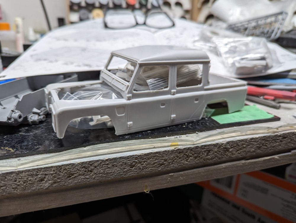
More Bond, James Bond stuff. Except it's the bad guys this time. Nicely done conversion for the recent Revell Land Rover.

-
Considering ZM Bf-109 for next build.......
BlrwestSiR replied to JohnB's topic in Modelling Discussion
Never built the Hasegawa one but I completely botched the Eduard version. Unless that was a Tempest? -
a-20g Art Scale Kit - 1:32 A-20 G canopy mask
BlrwestSiR replied to Fran's topic in Aircraft Reviews
The kit's not out yet and there's AM already for it and an important one at that. Great to see it fits and adheres well. Carl -
Looking good Martin. Quite a bit of reworking there but you're making it look easy.
-
You can never have too many Spitfires. The new Airfix Spitfire kit is one I've been debating about getting. It wouldn't fit in with the rest of the Spitfires I've built (11) or the 9 still in the stash. But if I built it completely opened up, it could work...
-
What is on your bench right now ? Share a picture :)
BlrwestSiR replied to Martinnfb's topic in Modelling Discussion
Looks great and it's even better when you're having fun. -
LSM Modelling News 2023 merged Fran and Artful69’s threads
BlrwestSiR replied to Fran's topic in Modelling Discussion
I think they're 1/48. The right side of that grouping has a 1/48 banner above the Mi-4 Hound. -
Italeri 1/35 Elco 80' Torpedo Boat PT-596
BlrwestSiR replied to Bomber_County's topic in Let’s Get Wet Group Build.
Phil, some nice work on the cannon and grab rails. The later PT boats were definitely much heavier armed than the earlier ones. -
Considering ZM Bf-109 for next build.......
BlrwestSiR replied to JohnB's topic in Modelling Discussion
Mines not finished. I'm still not sure where it went wrong but the dihedral on my build is out the window. Looks like a banana . Wing root gaps are fine so can't figure out where it went wrong. I think if you do it with the cowls open, it makes things much easier.